
VBModular Overfolder DiY Module rev1
User Manual and Build Document
(look below for REV2!!!)
Hello, and thank you for for purchasing the VB Modular Overfolder! We are certain you will be happy with the gnarly sounds you can make with it!
User Manual
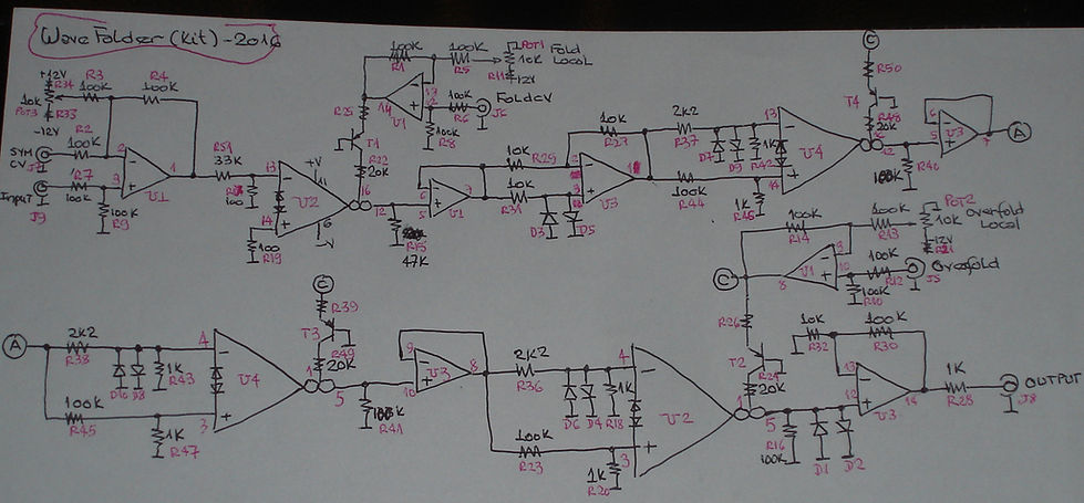
The Overfolder is a complex analog wave folder, containing two cascaded folding sections, labeled “Fold” and “Over”, as well as a symmetry control (“Sym”), which offsets the input signal for timbral variation. Each of these sections has a manual control knob as well as an external CV input. At the bottom of the module are the audio input and output. Right above are the three CV inputs, and above them are the manual controls. At low settings of the “Fold” and/or “Over” knobs, the module is silent, which allows for patching a voice without a VCA, for example. There are also certain settings where with no input signal present the module outputs various colors of noise, which is another alternative use for it. This is normal behavior for this circuit topology. The module works with audio as well as control voltages. In audio use it works best with Triangle, Sine and Saw waves from an oscillator. Square waves don’t work well, as they are not easily “folded”, and other sources that are not oscillator waves may or may not yield useable/interesting results. Definitely get acquainted with it using a sine or triangle wave before you start experimenting with different sound sources.
Building the Kit
The build is simple. You can follow the video manual, It’s the SDIY Tutorial #4 in the Synth Diy Guy youtube channel. If you google “Overfolder Kit” it should be one of the first hits.
Mount and solder all diodes (minding polarity) and resistors. Then the IC sockets, capacitors (minding polarity on the two electrolytic caps) and transistors (watch out for the inverted transistor, more info below). Then the headers. Don’t confuse the 2k2 resistors with the 22k ones!
The panel components (jacks and pots) get mounted on the opposite side of the Silk Screen! Only the resistors go on the silk screened side, the pots and jacks go on the opposite side to the graphics.
Don’t solder any of the pots or jacks until after you’ve secured them to the panel. The pots are slightly shorter than the jacks, so they get lifted slightly from the PCB. This is normal.
Make sure you clip off the small positioning tabs in front of the potentiometer shafts, or they’ll sit crooked against the panel. (I might have done this for you already)
TRANSISTOR T4 is inverted on the silk screen! Install it the other way around.
Any questions, comments or issues, please email us at vbrazilmodular@gmail.com or synthdiyguy@gmail.com
HAVE FUN!
Bill of Materials
Resistors: (1/6W 1% small resistors like mouser part# 603-MFR-12FTF52-100K)
2 X 100 Ohms R17, R19
7 X 1k Ohms R18, R20, R28, R42, R43, R46, R47
7 X 2k2 Ohms R11, R21, R33, R34, R36, R37, R38
4 X 10k Ohms R27, R29, R31, R32
8 X 22k Ohms R22, R24, R25, R26, R39, R48, R49, R50
1 X 33k Ohms R51
4 X 47k Ohms R15, R35, R52, R53
20 X 100k Ohms R1, R2, R3, R4, R5, R6, R7, R8, R9, R10, R12, R13, R14, R16, R23, R30, R40, R41, R44, R45
Semiconductors:
2 X TL074 U1, U3
2 X LM13700 U2, U4
10 X 1N4148 Diode (All “D”s: D1, D2….)
4 X BC557 Transistor T1, T2, T3, T4 (Attention, T4 is inverted in the graphics, please install it inverted!)
Capacitors:
8 X 0.1uf/100V ceramic C1, C2, C3, C4, C5, C6, C8, C9
2 X 10uf/35V Electrolitic C7, C10
Hardware:
3 X Pots - 10k Lin Pots 1, 2, 3
3 X Knobs
5 X 3.5mm mono jacks (PJ301BM) J5, J6, J7, J8, J9
2 X 14 pin IC socket
2 X 16 pin IC socket
1 X Right Angle Header (5 pin) J4
1 X Right Angle Header (10 pin) J2
1 X Boxed Power Header J10
The kit also includes mounting screws, power cable, and the 3 PCBs (Panel, Hardware and Circuit)
Overfolder Rev2
Build Doc and Manual
Hello, and thank you for purchasing the VB Modular Overfolder Rev2! We are certain you will be happy with the gnarly sounds you can make with it!
The Rev2 is practically the same module as the Rev1, only that it’s now a skiff friendly PCB sandwich with both boards parallel to each other. If you see two large holes on both PCBs (for the mounting screws and spacers) then you have the Rev 2. The only other change is the addition of three 33pf capacitors which reduce the noise in normal operation.
User Manual
The Overfolder is a complex analog wave folder, containing two cascaded folding sections, labeled “Fold” and “Over”, as well as a symmetry control (“Sym”), which offsets the input signal for timbral variation. Each of these sections has a manual control knob as well as an external CV input. At the bottom of the module are the audio input and output. Right above are the three CV inputs, and above them are the manual controls. At low settings of the “Fold” and/or “Over” knobs, the module is silent, which allows for patching a voice without a VCA, for example. There are also certain settings where with no input signal present the module outputs various colors of noise, which is another alternative use for it. This is normal behavior for this circuit topology. The module works with audio as well as control voltages. In audio use it works best with Triangle, Sine and Saw waves from an oscillator. Square waves don’t work well, as they are not easily “folded”, and other sources that are not oscillator waves may or may not yield useable/interesting results. Definitely get acquainted with it using a sine or triangle wave before you start experimenting with different sound sources.
Building the Kit
The build is simple. You can follow the video manual, It’s the Kit Review # 14 in the Synth Diy Guy youtube channel. If you google “Overfolder Kit” it should be one of the first hits.
Mount and solder all diodes (minding polarity) and resistors. Then the IC sockets, capacitors (minding polarity on the two electrolytic caps) and transistors. Then the headers. Don’t confuse the 2.2k resistors with the 22k ones!
The headers get soldered on the back of each PCB, so the sides with no silk screen oppose each other and the mounting screw holes line up. 2 hex spacers and 8 m3 screws are included in the kit. 4 screws are for securing the boards together with the spacers, and the other 4 are for mounting the module on your rack.
Don’t solder any of the pots or jacks until after you’ve secured them to the panel. The pots are slightly shorter than the jacks, so they get lifted slightly from the PCB. This is normal.
Any questions, comments or issues, please email us at vbrazilmodular@gmail.com or synthdiyguy@gmail.com
This document is also available, with added content such as schematics, at: https://synthdiyguy.wixsite.com/vbmodulardiy
HAVE FUN!
Bill of Materials
Resistors: (1/6W 1% small resistors like mouser part# 603-MFR-12FTF52-100K)
2 X 100 Ohms R17, R19
7 X 1k Ohms R18, R20, R28, R42, R43, R46, R47
7 X 2k2 Ohms R11, R21, R33, R34, R36, R37, R38
4 X 10k Ohms R27, R29, R31, R32
8 X 22k Ohms R22, R24, R25, R26, R39, R48, R49, R50
1 X 33k Ohms R51
4 X 47k Ohms R15, R35, R52, R53
20 X 100k Ohms R1, R2, R3, R4, R5, R6, R7, R8, R9, R10, R12, R13, R14, R16, R23, R30, R40, R41, R44, R45
Semiconductors:
2 X TL074 U1, U3
2 X LM13700 U2, U4
10 X 1N4148 Diode (All “D”s: D1, D2….)
4 X BC557 Transistor T1, T2, T3, T4
Capacitors:
7 X 0.1uf/100V ceramic C1, C2, C3, C4, C5, C8, C9
3 X 33pf/100V ceramic C6, C11, C12
2 X 10uf/35V electrolytic C7, C10 (you may opt to solder these on the back of the board to help with clearance for tight skiffs)
Hardware:
3 X Pots - 10k Lin Pots 1, 2, 3
3 X Knobs - White D Shaft Davies 1900 or similar
5 X 3.5mm mono jacks (PJ301BM) J5, J6, J7, J8, J9
2 X 14 pin IC socket
2 X 16 pin IC socket
Male and Female Headers (4 pin) J3, J4 (attention, these go on the back of the board, opposite the silk screened graphics)
Male and Female Headers (10 pin) J1, J2 (attention, these go on the back of the board, opposite the silk screened graphics)
1 X 10 pin Boxed Power Header J10
The kit also includes mounting screws, screws and spacers, power cable, and the 3 PCBs (Panel, Hardware and Circuit)
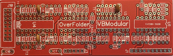
This is the mod to make Rev 1 into Rev 2. Just add three 33pf ceramic capacitors in parallel with the following three resistors: R15, R40 and R41. The image to the left shows you where they go.
Vinicius Brazil from Rio de Janeiro is now designing kits for the SDIY enthusiast!
We are two people who are passionate about modular synths and SDIY.
Vinicius Brazil is the designer. With over 40 years experience as a top porfessional in Electronic Engineering and Project Management in Rio de Janeiro, Brazil, Vinicius' true passion has always been music and music technology. He started designing and building Eurorack modular synths in 2010, and since 2016 has begun designing DIY kits as well.
Quincas Moreira, AKA Synth DiY Guy, is a sound designer and producer from São Paulo, Brazil, based in Mexico City. He has fallen in love with modular since he moved to Mexico in 2011, and since 2014 has been working with Vinicius as a test pilot for his modules, as well as producing videos, writing manuals, making connections and serving coffee for VB Modular.
From Brazil, with Love
Get in touch with us!
